Back to Projects

Project

Warman Challenge Robot

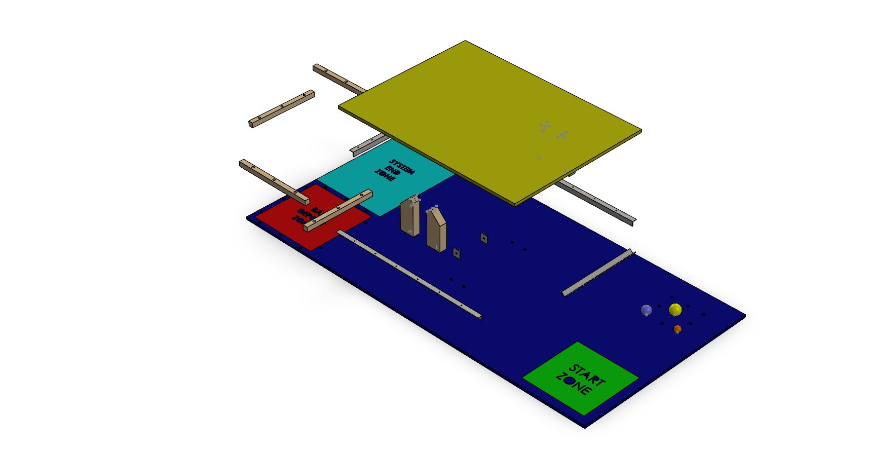
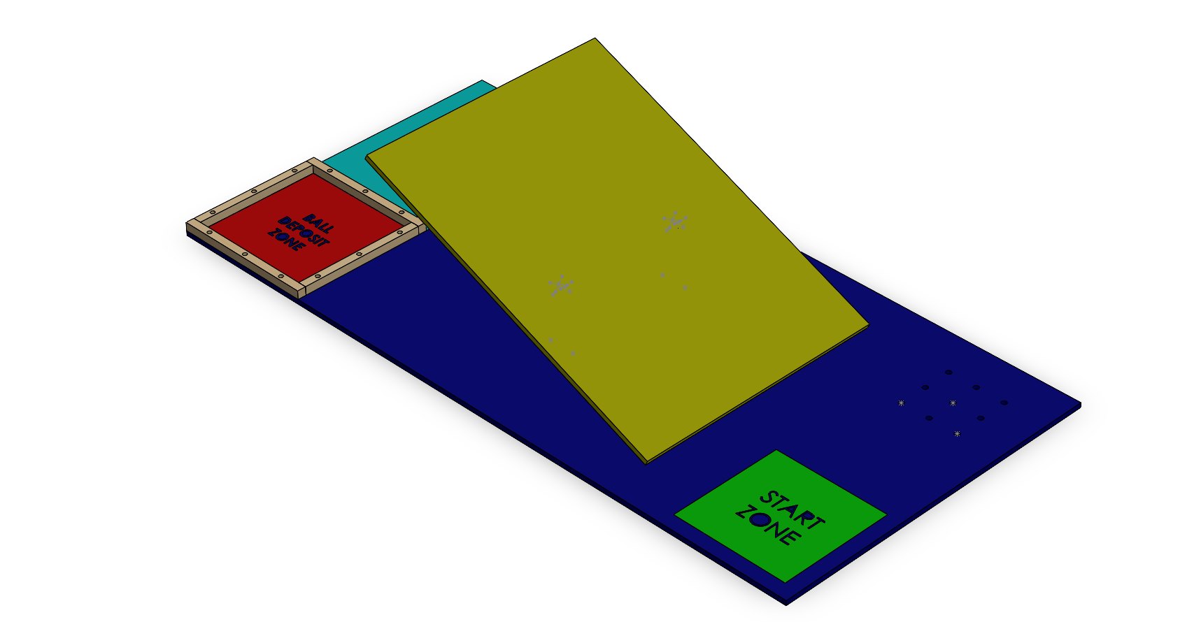
Robot mechanism design for a Warman subsystem, focused on ball retention, servo-actuated release gates and flaps, retainer geometry, tolerance-sensitive fit, CAD iteration, and prototype review.

Warman Challenge robot page showing mechanism design, CAD iteration, ball-retainer assemblies, servo-actuated release concepts, prototype visuals, and test-planning material.

  • Robotics
  • Mechanisms
  • CAD
  • Prototyping
  • Prototype Review
  • Robot Hardware
Warman Challenge Robot visual 1
Project imageExploded track assembly and subsystem layout
01

Overview

This project is presented as robot mechanism and subsystem design work for a Warman Challenge robot.

The page uses CAD screenshots and prototype visuals to show how the ball-retention and release mechanism evolved toward a testable competition subsystem.

02

Problem

The robot needed a compact subsystem for retaining and releasing balls under competition-style constraints.

That made the work a useful exercise in retainer geometry, servo-actuated gates and flaps, mechanism packaging, tolerance-sensitive fit, manufacturability, and test-planning.

03

My Role

  • Worked through CAD and mechanism layout for the ball-retention and release subsystem
  • Developed retainer geometry and servo-actuated gate/flap concepts
  • Prepared prototype and CAD visuals for review
  • Considered tolerance-sensitive fit, fabrication, service access, and testing constraints
04

Process

  1. Mechanism layout

    The work focused on ball-retainer geometry, release gates and flaps, servo actuation, and how the subsystem fit inside the wider robot.

  2. CAD iteration

    CAD screenshots record changes to assemblies, sheet-metal style parts, gate geometry, and tolerance-sensitive interfaces.

  3. Prototype review

    Prototype and testing-intent visuals helped review access, movement, fit, and likely adjustment points without claiming full mechanism validation.

05

Key Decisions

Retainer geometry

The subsystem needed retainer geometry that could hold balls in position while still allowing a controlled release path.

Servo-actuated gates and flaps

Servo-actuated release concepts were explored through CAD and prototype review, with attention to motion, clearance, and packaging.

Fit and access

The design work kept tolerances, assembly access, fabrication, adjustment points, and later testing in view.

06

Project Material

Selected project material used to show CAD, component, prototype, or documentation details.

Warman Challenge Robot visual 1
Fig. 01Exploded track assembly and subsystem layout
Warman Challenge Robot visual 2
Fig. 02Track assembly view without payloads
07

Outcome

A robot mechanism page showing CAD iteration, retainer and gate concepts, prototype visuals, and testing-oriented subsystem records.

Supports practical robot hardware work through mechanism packaging, tolerancing awareness, serviceability, manufacturability, and test-planning.

08

Next Steps

  • Mechanism concepts need physical testing because release behaviour and fit are difficult to judge from CAD alone.
  • Clear CAD and prototype visuals make tolerance, actuation, and adjustment decisions easier to discuss.
  • Add concise annotations around retainer geometry, gate movement, and servo placement if public images are expanded later.
  • Keep any raw CAD or source files private until ownership and release checks are complete.