Back to Projects

Project

Confined-Space Inspection Robot

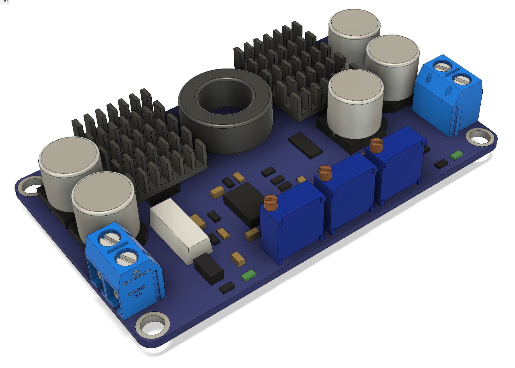
Prototype-stage compact mobile robot design covering wheel/chassis layout, camera and controller integration, motor-driver-battery packaging, wiring paths, protection, and service access.

Compact inspection-robot packaging study showing how chassis geometry, wheels, motors, drivers, battery storage, camera hardware, wiring, and Raspberry Pi layout fit into a small mobile platform.

  • Robotics
  • Mobile Robot
  • Robot Hardware
  • Sensing
  • System Integration
  • Packaging
Confined-Space Inspection Robot visual 1
Project image18650 battery packaging consideration
01

Overview

This capstone project developed a confined-space inspection robot concept around compact mechanical packaging, mobility, camera integration, controller placement, power layout, and service access.

The page uses CAD screenshots, component visuals, notes, and prototype photos to explain prototype-stage design decisions while keeping raw source files out of the public site.

02

Problem

A confined-space inspection robot needs to carry drive hardware, power storage, controller electronics, camera hardware, wiring, and protective structure inside a small mobile platform.

The mechanical challenge was to balance mobility, low centre of gravity, service access, cable routing, component protection, and maintenance needs without making the chassis too bulky.

03

My Role

  • Developed CAD and packaging concepts for the compact robot chassis
  • Worked through wheel/chassis, motor, motor-driver, battery, Raspberry Pi, and camera layout decisions
  • Considered low-centre-of-gravity packaging, service access, protection, and maintenance constraints
  • Prepared prototype photos and CAD visuals to communicate subsystem integration and test-planning intent
04

Process

  1. Chassis packaging

    The design work centred on fitting the wheelbase, chassis envelope, motors, electronics, camera hardware, and power storage into a compact inspection-robot form factor.

  2. Drive and power layout

    Motor, driver, battery, and wiring placement were treated as mechanical packaging problems, with attention to centre of gravity, protection, cable paths, and access for assembly or maintenance.

  3. Sensing and controller integration

    The camera/sensing and Raspberry Pi/controller layout needed clear mounting space, cable paths, and protected locations while preserving inspection visibility and mobility.

  4. Prototype review and test planning

    Prototype photos and CAD views support review of packaging choices, service access, protection, maintenance points, and future test planning at prototype stage.

05

Key Decisions

Compact mechanical architecture

The project shows trade-offs across chassis geometry, wheel placement, drive components, power storage, controller hardware, camera placement, and inspection payload space.

Serviceability and protection

Battery, driver, controller, and camera placement were framed around access, cable routing, maintenance, protection, and low-centre-of-gravity layout.

Integrated subsystem packaging

The robot hardware work connects CAD packaging, prototype iteration, test planning, service access, component protection, and integration records.

06

Project Material

Selected project material used to show CAD, component, prototype, or documentation details.

Confined-Space Inspection Robot visual 1
Fig. 0118650 battery packaging consideration
Confined-Space Inspection Robot visual 2
Fig. 02LTC3780 power module
07

Outcome

A prototype-stage robot hardware record showing compact chassis packaging, wheel and drive layout, electronics and power integration, camera placement, prototype visuals, and test-planning notes.

Relevant to mechanical and robot-hardware engineering because it connects CAD packaging, sensor integration, serviceability, low-centre-of-gravity layout, protection, and prototype iteration.

08

Next Steps

  • Compact robot design needs electronics, power, drive, and sensing hardware to be treated as mechanical packaging constraints from the start.
  • CAD views, prototype photos, and integration notes make serviceability, centre of gravity, protection, and assembly trade-offs easier to review.
  • Add annotated CAD views showing centre-of-gravity intent, maintenance access, wiring paths, and protected component zones if reviewed material is available.
  • Future sensor work could investigate vibration or condition-monitoring use cases only after validated measurement data and reviewed notes are available.