Back to Projects

Project

Additive Manufacturing Plier Project

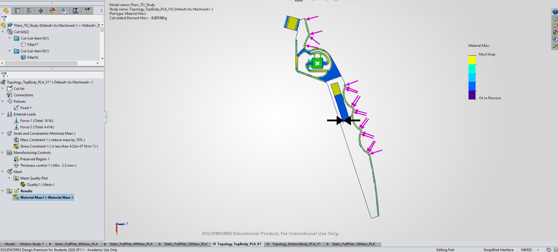
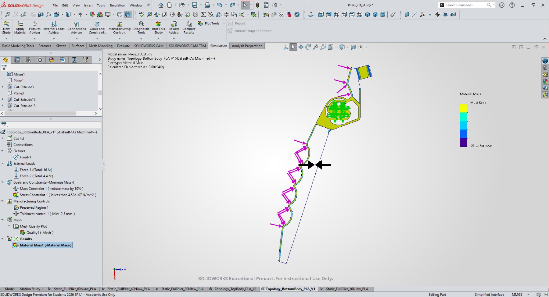
DfAM plier project using topology optimisation, CAD iteration, static-study visuals, slicer setup, support settings, and manufacturability trade-offs for a printed mechanical tool.

Mechanical tool design shaped by additive manufacturing constraints, showing concept development, topology optimisation, SolidWorks static-study visuals, slicer preparation, support settings, and manufacturability trade-offs.

  • Additive Manufacturing
  • Topology Optimisation
  • CAD
  • Static Study
  • Slicing
  • 3D Printing
Additive Manufacturing Plier Project visual 1
Project imageTopology-optimised top body result
01

Overview

This project is presented as design for additive manufacturing and mechanical tool design work.

The page uses concept, CAD, topology optimisation, static-study, and slicer visuals to show how a printable plier geometry was iterated and prepared.

02

Problem

The design challenge was to develop a printable plier geometry while accounting for additive manufacturing constraints.

The work connects material use, geometry reduction, static-study outputs, print orientation, support strategy, wall and infill settings, manufacturability, and design records without overstating mechanical performance.

03

My Role

  • Developed concept and CAD geometry for a printable plier
  • Used topology optimisation and static-study screenshots as design material
  • Prepared slicer and support-setting visuals to communicate print preparation and manufacturability decisions
04

Process

  1. Concept to CAD

    The project moved from concept development into CAD geometry that could be checked, iterated, and prepared for additive manufacturing.

  2. Optimisation and checking

    Topology optimisation and static-study visuals were used to reason about material placement and likely load paths, while keeping the page limited to supported static-study outputs.

  3. Print preparation

    Slicer visuals show how the CAD geometry moved toward a printable part with orientation, wall, infill, support, and setup constraints visible.

05

Key Decisions

DFM for additive manufacturing

The project highlights printability, material use, support settings, wall and infill choices, and geometry decisions.

Static-study record

CAD, topology optimisation, static-study outputs, print-preparation records, and manufacturability trade-offs are kept visible together.

06

Project Material

Selected project material used to show CAD, component, prototype, or documentation details.

Additive Manufacturing Plier Project visual 1
Fig. 01Topology-optimised top body result
Additive Manufacturing Plier Project visual 2
Fig. 02Topology-optimised bottom body result
07

Outcome

A project page showing concept-to-CAD development, topology optimisation, static-study visuals, slicer setup, and print-preparation decisions.

Supports mechanical design through DfAM, CAD iteration, manufacturability, print preparation, static-study outputs, and design records.

08

Next Steps

  • Manufacturability decisions should be visible in the design record, not hidden after the final CAD image.
  • Static-study and slicer outputs make the design process clearer than a finished model alone.
  • Add concise annotations explaining the key topology, static-study, support, and print-preparation decisions.
  • Prepare source CAD or print files for public release only after cleanup and release notes.